Single beam systems provide no information on target location and the measured echo level combines the effect of TS and location in the beam (Fig. 6). TS distributions have to be estimated from echo statistics.
Dual beam systems transmit sound on a narrow beam and receive the echo on both this narrow beam and a wide beam. The ratio between the two echo levels is used to calculate the distance from the target to the center of the beam and allows for compensation for directivity in the calculation of TS.
Split beam transducers calculate target location in three dimensions by comparing phase deviations of the returning signal in 4 sections of the transducer. This also allows for compensation of directivity and calculation of TS and for calculation of fish swimming speed in situ (Arrhenius et al. 2000, Torgersen and Kaartvedt 2001). In addition, split beam units can be elliptical – dual beam units are always circular.
With current developments in both hardware and software, we recommend acquiring split beam systems. While more expensive, the increased capabilities of a split beam system are worth the cost.
Figure 7. Transducer configurations. Single beam transducers give information on 1 dimension (depth), dual beam transducers gives information on 2 dimensions, depth and distance from the acoustics axis, and split beam transducers gives information on the location in all three dimensions. Reproduced with permission from Simrad A/S.
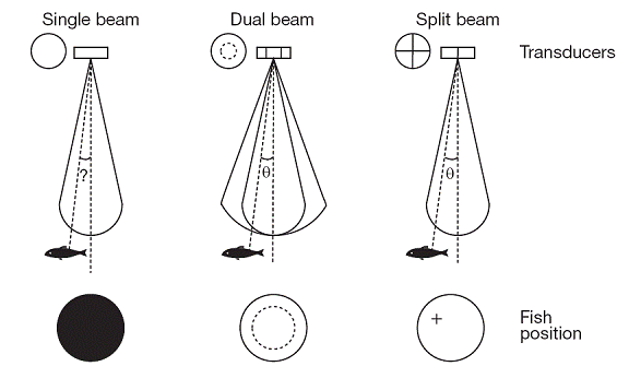

Figure 7. Transducer resolution and beam width. From Brandt (1996). Reproduced with permission from the American Fisheries Society © AFS.