Standard sphere preparation
The standard sphere should be suspended in a monofilament cradle (Fig. 12). In order to reduce the presence of air bubbles, the cradle should be tied tightly. Prior to deployment, the sphere should be dipped in liquid dish soap to further reduce the likelihood of air bubble entrapment.
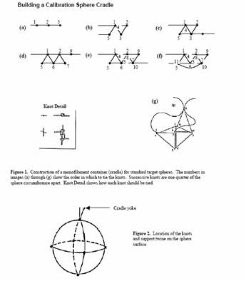
Figure 12. Monofilament calibration sphere cradle tying instructions. From Biosonics.
Data management and recording
Like all survey data, calibration data collection must be documented in detail.
Optimal sphere depth
The calibration sphere must be positioned below the transducer outside of the transducer near-field zone:
We consider the minimum distance for the standard target to be more than 3 times the near-field range calculated with [Equation 16]. For most cases, a distance between transducer and target of 5 to 10 m is sufficient, but greater distances (>10 m) may be optimal to minimize the effect of sphere motion.
Temperature
A vertical temperature profile should be obtained to calculate sound speed prior to every calibration. The profile must encompass the calibration depths. This profile should be compared to temperature profiles obtained during the survey to ensure similar physical environmental conditions between the calibration exercise and the survey. Calculate sound speed and absorption from the average temperature between the transducer and the target. The TS of standard targets has a small dependency on temperature, and the TS of the target should therefore be corrected for temperature. In this case, temperature at the calibration sphere should be used.
Software
Echosounder manufacturers provide detailed instructions for calibrating their systems. These instructions must be followed to ensure proper calibration and system stability. The manufacturers may also provide software. However, we recommend that the same software is used for analysis of calibration data as for analysis of the survey itself. For example, different methods for single target detection are implemented in Echoview and will give slightly different values. Therefore, use the same method to analyze the calibration ball as used to analyze fish echoes. Because software upgrades occur, software version identification (both calibration software and echosounder software) should be documented.